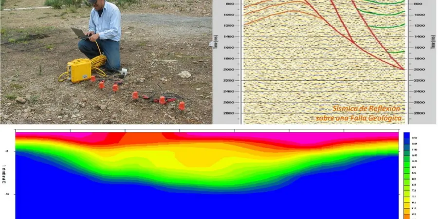
The geophone string stretches across the site, each node spiked firmly into the damp Meath soil. A swift hammer blow against the steel plate sends a compressional wave racing through the subsurface layers beneath Navan. This is the start of a seismic refraction and reflection survey, tracing energy paths that bend at every geological boundary. The field crew monitors the seismograph screen while the first arrivals register—each wiggle on the trace translates directly to a velocity layer in the subsurface model. In Navan's undulating terrain, where Carboniferous limestone sits beneath variable glacial till, seismic refraction provides the continuous bedrock profile that an isolated borehole on its own cannot deliver. When the target is deeper than 30 metres, we switch to reflection acquisition with a longer spread and a heavier source, capturing high-resolution images of fault zones and buried channels that influence pile design and excavation stability.
A velocity anomaly below 1,500 m/s in limestone terrain is rarely benign—it typically signals a dissolution feature that demands investigation before foundation loads are applied.
Methodology and scope
Local considerations
A six-storey apartment block planned on the outskirts of Navan sat directly above a buried doline—a bowl-shaped depression in the bedrock roof filled with soft, compressible clay. Boreholes missed the edges of the feature by less than three metres. The seismic refraction profile, however, showed a sharp velocity drop from 3,200 m/s to 980 m/s over a 14-metre-wide zone at 11 metres depth. Without that tomographic slice, the structural engineer would have designed shallow footings over a hidden sinkhole. The consequence: differential settlement severe enough to crack partition walls and shear service risers within the first two years of occupancy. Karst-related ground collapse is a real risk across the Navan area, and the cost of a seismic survey is marginal compared to the expense of remedial grouting or legal claims after building completion. Insurance underwriters increasingly request geophysical evidence of bedrock continuity before issuing latent defect cover for multi-storey structures on limestone terrain.
Applicable standards
Eurocode 7 (EN 1997-2:2007) – Ground investigation and testing, ISRM Suggested Methods for Seismic Testing, ASTM D5777-18 – Standard Guide for Using the Seismic Refraction Method, I.S. EN ISO 22475-1 – Geotechnical investigation and testing
Associated technical services
Seismic Refraction Tomography
Multiple shot points per spread, recorded on 24- or 48-channel seismographs, processed with iterative inversion to produce 2D P-wave velocity sections. Ideal for mapping top-of-rock, rippability, and detecting karst features to depths of 30–40 metres.
Seismic Reflection Profiling
Higher-energy source and longer offsets to image deeper horizons beyond the refraction depth limit. Used for fault mapping, basin geometry, and deep cavity detection where the target exceeds 50 metres below ground level.
Combined Geophysical Surveys
Integrated seismic, electrical resistivity, and MASW acquisition along the same lines. The multi-parameter approach reduces ambiguity when interpreting complex limestone–overburden interfaces and provides shear-wave velocity data for seismic site classification.
Typical parameters
Frequently asked questions
How much does a seismic tomography survey cost for a typical Navan site?
For a standard refraction spread with 24 geophones and 5–7 shot points, budgets in the Navan area generally range from €2,200 for a single profile up to approximately €5,260 for a multi-line survey with reflection acquisition. The final figure depends on line length, access conditions, and whether resistivity or MASW is added to the scope.
Can seismic refraction work on asphalt or concrete surfaces in urban Navan?
Yes, but the coupling method changes. Instead of spiked geophones, we use flat-base sensors with a viscous couplant or sandbags on hard surfaces. The energy source also shifts—typically a weight drop or an accelerated drop hammer on a tripod—to deliver sufficient energy through the pavement layer without damaging it.
What is the difference between seismic refraction and reflection for a construction project?
Refraction uses the critically refracted head wave that travels along velocity boundaries and is best for mapping the top of bedrock and shallow layer velocities. Reflection records the energy that bounces off impedance contrasts and is suited for deeper targets, such as fault planes or cavity roofs beyond 40 metres. Many Navan projects use refraction for foundation design and reflection when investigating suspected deep mine workings or regional fault structures.
How long does a seismic survey take on site, and will it disrupt site preparation work?
A single refraction line of 72 metres typically takes a two-person crew about 90 minutes to lay out, shoot, and pack up. The footprint is minimal—no drilling, no heavy plant—so other site activities can continue nearby. Data processing and tomographic inversion are completed off-site within three to five working days.